Evacuation Diagrams: Compliance Tips
Evacuation diagrams are mandatory for Australian workplaces under AS 3745-2010. They guide safe evacuations during emergencies, reducing confusion and panic. These diagrams must include essential features like "You Are Here" markers, exit routes, fire equipment locations, and assembly points. Compliance requires proper placement, accurate orientation, and updates every five years. Avoid common errors like incorrect markers, outdated diagrams, or non-compliant colours. Properly designed and maintained diagrams can reduce evacuation times by up to 30%.
Key points:
- Mandatory features: Title, facility details, exit routes, fire equipment, assembly points, legend.
- Placement: 1200–1600 mm above the floor, visible, not on fire-rated surfaces.
- Updates: Validity cannot exceed five years.
- Optional additions: First aid kits, AEDs, or mobility device locations.
Using durable materials and ensuring compliance ensures diagrams remain effective in emergencies.
🔥 How to Install Evacuation Diagrams the RIGHT Way! ✅ AS3745 Compliant Guide
sbb-itb-9950c92
Required Features of an Evacuation Diagram Under AS 3745-2010
AS 3745-2010 Evacuation Diagram Mandatory Requirements Checklist
Elements Required by the Standard
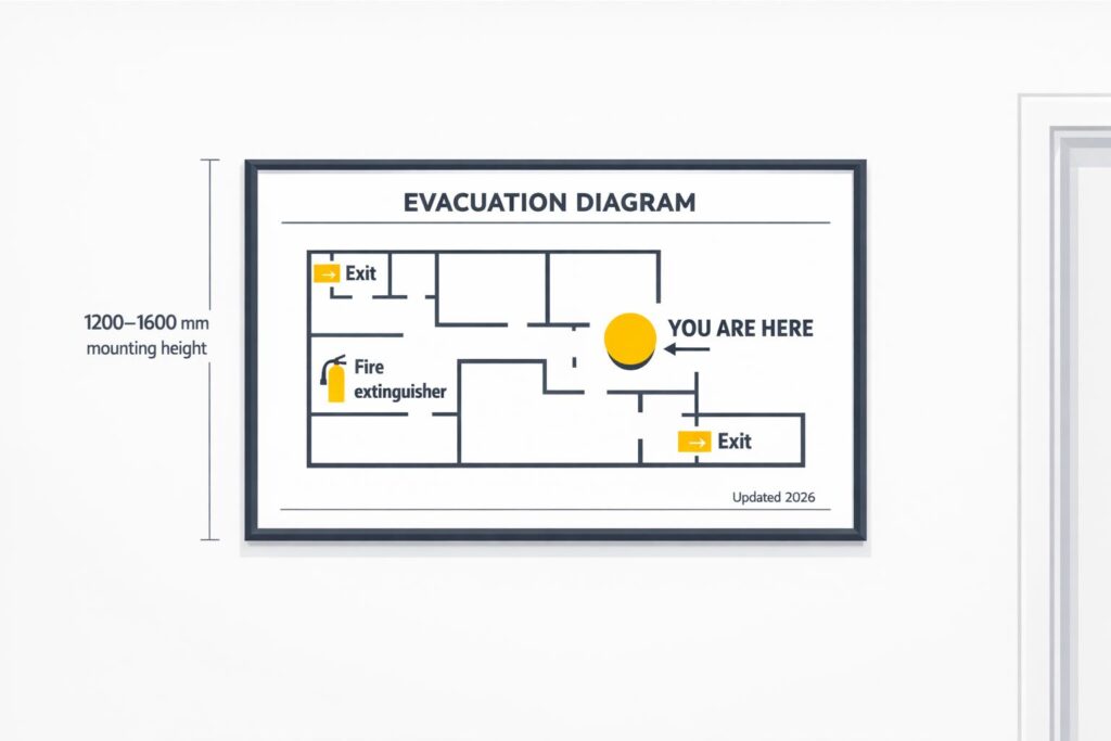
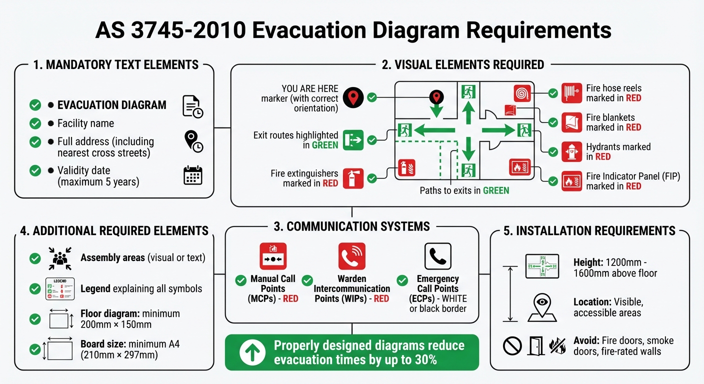
AS 3745-2010 lays out specific requirements for evacuation diagrams to ensure clarity and usability in emergencies. These diagrams must include the title "EVACUATION DIAGRAM", the facility’s name, its full address (including the nearest cross streets), and a validity date that cannot exceed five years [1][4][6].
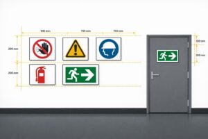
A "YOU ARE HERE" marker must accurately reflect the occupant’s position and orientation within the building [1][4]. Exits should be highlighted in green, along with the paths leading to them [1][2][4]. Firefighting equipment, such as fire extinguishers, hose reels, fire blankets, hydrants, and the Fire Indicator Panel (FIP), must be marked in red [1][4][6].
Communication systems also require distinct representation: Manual Call Points (MCPs) and Warden Intercommunication Points (WIPs) are shown in red, while Emergency Call Points (ECPs) are either white or feature a black border [1][4]. Assembly areas must be indicated, either visually or in text, and the diagram must include a legend explaining all symbols used [1][4]. The floor or area diagram itself must measure at least 200 mm × 150 mm and be mounted on a board no smaller than A4 size (210 mm × 297 mm) [1][4][3].
By adhering to these guidelines, facilities can ensure their diagrams meet compliance standards and are easy to understand during emergencies.
Common Compliance Errors to Avoid
Despite the clear requirements, non-compliance issues are common and can undermine the effectiveness of evacuation diagrams. One frequent mistake is the absence or incorrect orientation of the "You Are Here" marker, which can disorient people during evacuations [1]. Another common error is misusing colours, such as marking exits in red instead of green, which goes against the standard [1].
Failing to include a legend or using symbols that don’t align with the legend can render the diagram confusing and non-compliant [1][4]. Outdated diagrams are another issue – many facilities neglect to update diagrams after structural changes or continue using them beyond the five-year validity period [3]. Missing essential details like the facility’s full address or validity date also affects compliance [1][6]. Additionally, placing diagrams on fire doors, smoke doors, or fire-rated walls may breach the Building Code of Australia (BCA) and should be avoided [3][6].
Avoiding these errors ensures diagrams remain effective and compliant with AS 3745-2010.
Placement and Orientation Requirements for Evacuation Diagrams
Where to Install Evacuation Diagrams
Evacuation diagrams should be installed in areas that are easy to access and frequently used. Typical locations include corridors, stairwells, lift lobbies, communal spaces, and near exits [1]. In hotels and apartment complexes, diagrams must also be displayed on individual unit entrance doors and within fire stairs [3].
The Emergency Planning Committee (EPC) is responsible for deciding the quantity and placement of diagrams within a facility. Their goal is to ensure comprehensive coverage along the "path of travel" throughout the building. Avoid placing diagrams on fire-rated surfaces; instead, mount them on nearby walls [3]. Once locations are determined, ensure the diagrams meet height and visibility standards for clarity.
Height and Visibility Requirements
According to AS 3745-2010, evacuation diagrams should be mounted between 1200 mm and 1600 mm above the finished floor level [7]. This height range ensures the diagrams are easily visible and readable during emergencies.
"The evacuation diagram should be positioned at a height not less than 1200 mm and not more than 1600 mm above the floor." – CMG Fire and Safety [5]
The diagrams should be at least A4 in size, with A3 recommended when extra details are included [7]. Ensure nothing blocks the diagrams, such as furniture, plants, or open doors [6]. To maintain their condition over their five-year lifespan, consider using protective frames like aluminium snap-lock frames.
Aligning Diagrams with Building Layout
Once the diagrams are mounted at the correct height and are clearly visible, it’s crucial to confirm that their layout matches the actual building structure. For example, if the diagram shows an exit to the left, the physical exit must also be to the left. This alignment is critical to avoid confusion during emergencies [1].
The "YOU ARE HERE" marker must accurately indicate the user’s location and align with the building’s egress routes [1]. Before finalising installation, conduct an on-site check to ensure the diagram’s orientation mirrors the actual building layout. This step can greatly improve the diagram’s effectiveness, potentially reducing evacuation times by up to 30% [1].
Optional Features to Improve Evacuation Diagrams
Additional Details for Improved Safety
To address specific safety needs, businesses can enhance evacuation diagrams by incorporating optional features. These may include marking first aid stations and kits (depicted as a white cross on a green background), Automated External Defibrillators (AEDs), spill response kits, and showing door opening directions at exits. Adding the locations of fire and smoke doors and a North direction indicator can also help improve orientation and overall safety measures [1]. Emergency contact numbers, fire orders, and tailored response procedures can be included based on decisions made by the Emergency Planning Committee [1].
"The emergency planning committee may decide to include additional information, such as… specialised evacuation devices for mobility-impaired occupants [and] locations of fire and smoke doors." – Activate Safety [1]
Key Tip: If these optional elements are added, the diagram size must increase from A4 to A3 (297 mm × 420 mm) for better readability and compliance. Similarly, the floor area representation should expand from 200 mm × 150 mm to at least 300 mm × 200 mm [6][5].
By considering these additions, businesses can better tailor their evacuation diagrams to their specific safety requirements.
Tailoring Diagrams for Specific Business Needs
Customising evacuation diagrams to reflect industry-specific hazards ensures a more effective emergency response. For instance, industrial and manufacturing facilities often include details like hazardous chemical stores, electrical switchboards, and solar power isolation points, which are critical for assisting emergency services [1][4].
In healthcare and aged care facilities, diagrams should account for specialised evacuation devices for mobility-impaired occupants. These facilities may also need to comply with AS 4083-2010 in addition to AS 3745-2010 [1][2].
Commercial offices and retail spaces can benefit from indicating features such as warden intercommunication points and electrical infrastructure locations [1]. The Emergency Planning Committee should assess which optional elements are most relevant to the facility’s specific risks. These enhancements work alongside the mandatory features to create a more comprehensive emergency preparedness plan.
Next, explore how essential safety signs, like those offered by PXP Safety, can further help meet AS 3745-2010 compliance standards.
Meeting Compliance with Custom Safety Signage
Customisation Options at PXP Safety
Evacuation diagrams are required to adhere to AS 3745-2010 standards, and they must be crafted from materials that can withstand Australia’s demanding conditions. In emergencies, having clear, durable, and compliant diagrams is essential. PXP Safety ensures their products meet these needs by offering diagrams made with robust aluminium bases, UV protective film, and solvent-grade outdoor printing. These features combat fading and ensure that critical information remains visible when it’s needed most.
Selecting the right material plays a key role in maintaining long-term legibility. PXP Safety provides high-durability options like white or silver brushed Alupanel, suitable for both indoor and outdoor use, as well as anodised aluminium for industrial environments where corrosion is a concern. These materials not only meet the five-year validity requirement outlined in AS 3745-2010 but also maintain their clarity and reliability over time [1].
Fire Evacuation Block Plans from PXP Safety, compliant with AS 3745, start at $100.00 AUD for print-only services [8]. Beyond standard offerings, they also create custom signage tailored to specific business requirements. This includes adjustments in size, colour, and design, all while meeting the necessary technical specifications. These custom options ensure the signs are not only durable enough for Australian conditions but also meet strict compliance standards.
Meeting AS 3745-2010 Requirements with PXP Safety
PXP Safety goes beyond durability by ensuring every evacuation diagram fully complies with AS 3745-2010. Each diagram includes mandatory elements such as a title, validity date, facility details, exit routes, and equipment locations [1]. They also adhere to precise size and colour specifications, ensuring clarity and compliance [7] [1].
For businesses requiring additional safety information, such as first aid stations, AED locations, or electrical switchboards, PXP Safety integrates these details without compromising readability or size standards. This attention to detail can make a big difference – clear and well-placed evacuation diagrams have been shown to reduce evacuation times by up to 30% during emergencies [1].
Conclusion
Evacuation diagrams play a critical role in safeguarding lives during emergencies. The AS 3745-2010 standard provides a structured guide to ensure these diagrams communicate essential information effectively.
Proper placement is just as important as compliance. Diagrams should be installed in easily visible locations, away from fire doors, to maintain their safety function. Using long-lasting, compliant materials ensures the diagrams remain clear and readable over time, even under challenging conditions. Well-designed diagrams can even cut evacuation times by up to 30% during an emergency [1].
PXP Safety offers Fire Evacuation Block Plans tailored to meet Australian standards. Their designs include every essential detail, from the bold "EVACUATION DIAGRAM" heading to marked assembly points and equipment locations, ensuring clarity and reliability when it matters most.
FAQs
Who is responsible for evacuation diagram compliance?
The task of ensuring compliance with evacuation diagrams lies with the person conducting a business or undertaking (PCBU) or the facility manager. It’s their duty to make sure these diagrams are properly prepared, regularly maintained, and installed in line with Australian Standard 3745-2010.
When do evacuation diagrams need updating?
Evacuation diagrams need to be reviewed and updated at least once every 12 months or whenever there are changes to the building’s layout or safety features. This ensures they stay accurate and meet the requirements outlined in standards such as AS 3745-2010.
Where should evacuation diagrams be installed?
Evacuation diagrams need to be positioned in spots that are easy to see and access. Think areas like near exits, along corridors, in stairwells, or communal spaces. They should be mounted at a height between 1200 mm and 1600 mm from the floor. It’s also crucial that the diagrams are oriented correctly to clearly show the direction of exits, aligning with the requirements of Australian Standard AS 3745-2010.
Related Blog Posts
You may also be interested in

FAQs About Workplace Safety Signs in Australia
AS 1319 sign types, placement, materials and maintenance for workplace safety and WHS compliance in Australia.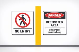
Restricted Area Signs vs. No Entry Signs
Compare No Entry and Restricted Area signs in Australian workplaces — meanings, design differences and AS 1319 compliance.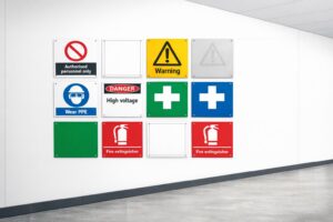
How to Spot Workplace Signage Gaps
Audit your workplace for missing, faded or non‑compliant signs under AS 1319 to reduce incidents and avoid WHS fines.
Symbol Design: Global Standards Explained
Explains ISO 7010 and ISO 3864: standard symbols, colours and sizing for clear, language‑free safety signage and AU compliance.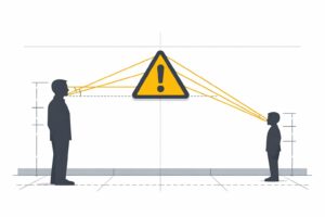
Hazard Sign Visibility Planner
Plan hazard sign placement for max visibility with our free tool. Ensure safety by finding the best spot, height, and angle—try it now!